10+ uml diagram key
Create your first class. Read Our UML Diagram Tutorial.

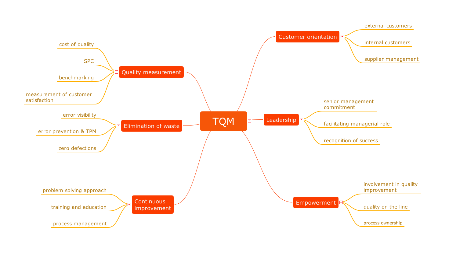
Cs 383 Software Engineering
GoF Design Patterns - Strategy.

. Here I will discuss guards in both UML 1x as well as UML 2. Types of UML Diagrams. ER Diagram of a Company.
To learn more about creating UML diagrams. You can draw UML diagrams online using our software or check out some UML diagram examples at our diagramming community. A strong entity will always have a primary key.
The work of Chen Bachman Brown Martin and others also contributed to the development of Unified Modeling Language UML widely used in software design. The relationship of two strong entities is represented by a single diamond. Heres a correct approach in my view and checked against Jacobson Fowler Larmen and 10 other references.
James Martin added ERD refinements. It allows us to understand the relationships between entities. The different team members or key members involved in Waterfall model development process are Technical Manager Developers Senior Developers Business analyst Technical Lead or System Architect or Solutions Architect or Technical Architect in the Design Phase and the Developers Senior Developers in the Coding phase.
Blend reverse engineering via GitUML with your literate custom code fragments and rich text narrative commentsstories - step by step so that viewers of the. UML stands for Unified Modeling LanguageIts a rich language to model software solutions application structures system behavior and business processesThere are 14 UML diagram types to help you model these behaviors. UML 1x component diagram.
They also provide detailed massenergy balance data along with stream composition and physical properties. Diagrams such as Figure 1 are often referred to as wiring diagrams because they show how the various software components are wired together to build your overall application. The lines between components are often referred to as connectors the implication being that some sort.
Strong entities are represented by a single rectangle. The key to Include and extend use case relationships is to realize that common with the rest of UML the dotted arrow between use cases is a dependency relationship. Entities and their Attributes are.
GoF Design Patterns - Memento. Difference between UML and ER diagram. AEST Available Monday to Friday from 6AM to 6PM PT key reenabled to fix bug 65417 updated per 63834.
How to create a UML class diagram in Gleek 1. Introduction of ER Model. Some relational model diagrams also include a key participation label to the left of the column names in the list of columns eg.
Dia Diagram Editor is capable of creating all manner of diagrams from electronic circuit diagrams and computer network diagrams to simple flowcharts for business projects. Objectives and Key Results 2. Use standard UML diagrams and follow the standard UML style and your box-and-line drawings are meaningful across the industry without 1 you having to provide a key to the meaning of the elements youve drawn and 2 the people youre sharing your design with making invalid assumptions because some of the boxes look just like.
Available M-F 800 am. It illustrates the general plant streams major equipments and key control loops. ER diagram of Bank Management System.
In 1987 Ivar Jacobson presented the first article on use cases at the OOPSLA87 conference. The most convenient approach should be to have a Jupyter notebook extension that dynamically generates diagrams of the classes defined in a notebook somehow like the variable inspector - possibly with the option to specify an alternative root like datetime in the first answer to creating UML charts by Pylintpyreverse within Jupyter labs console. Build Literate Code Map diagrams.
Bachman developed a type of Data Structure Diagram named after him as the Bachman Diagram. ER Diagram of Bank Management System. The concepts behind it are about organizing the way a device computer program or other often technical process works such that an entity or each of its.
UML state machine also known as UML statechart is an extension of the mathematical concept of a finite automaton in computer science applications as expressed in the Unified Modeling Language UML notation. Learn about UML BPMN ArchiMate Flowchart Mind Map ERD DFD SWOT PEST Value Chain and more. Association Class and Self Association.
Process Flow Diagram is a simplified sketch that uses symbols to identify instruments and vessels and to describe the primary flow path through a unit. Originally he had used the terms usage scenarios and usage. Application Services Map View.
UML 2x component diagram. The key to making a UML diagram is connecting shapes that represent an object or class with other shapes to illustrate relationships and the flow of information and data. He described how this technique was used at Ericsson to capture and specify requirements of a system using textual structural and visual modeling techniques to drive object oriented analysis and design.
More than 1000 predefined objects and symbols. It will be drawn as a standard rectangle with space for the attributes and methods. When you want more detail than a UML diagram can provide try building a Literate Code Map which is a new practical evolution of UML for todays code centric practical programmer.
Brown published works on real-world systems modeling. What may be more useful than this is a naming convention that makes it clear what is the primary key of a table easily done if you use surrogate keys by convention and what is a foreign key column. UML 25 Business Process Model and Notation BPMN 20 and Institute of Electrical.
This bank ER diagram illustrates key information about bank including entities such as branches customers accounts and loans. We can just name this Class. Add method with TAB and add at the end so that Gleek knows its a method.
To draw a guard on a sequence diagram in UML 1x you placed the guard element above the message line being guarded and in front of the message name. Guards are used throughout UML diagrams to control flow. Browse Tips for Better UML Diagrams.
Add an attribute with the TAB key to indent the code. Attributes of Bank Entity are Bank Name Code and Address. Easy to use Recommended in 89 of the user ratings.
In UML 1x a guard could only be assigned to a single message.

Object Oriented Design The Blog Of Colin Mackay

Cs 383 Software Engineering
What Is Activity Diagram In Software Engineering Quora

Cs 383 Software Engineering

Cs 383 Software Engineering

Uml Sequence Diagram Tutorial Lucidchart Sequence Diagram Diagram Activity Diagram

University Database Schema Diagram This Database Diagram Example Illustrates A University Database Schema Data Schema Database Design Class Diagram Database

Cs 383 Software Engineering

Cs 383 Software Engineering

Cs 383 Software Engineering
Login Module Uml Sequence Diagram Sequence Diagram Diagram Login
2

Cs 383 Software Engineering
Org Chart Diagram How To Draw A Hierarchical Organizational Chart Quality Issues In Heir Organization Mind Map Hierarchical Organizational Chart
Org Chart Diagram How To Draw A Hierarchical Organizational Chart Quality Issues In Heir Organization Mind Map Hierarchical Organizational Chart

Cs 383 Software Engineering
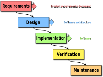
Cs 383 Software Engineering